#written in 68k ti-basic
Explore tagged Tumblr posts
Visit Tumblr Blog
Explore Tumblr blogs with no restrictions, modern design and the best experience.
Last Seen Tumblr Blogs


Fun Fact
If you dial 1-866-584-6757, you can leave an audio post for your followers.
Text
Bored in class

#my thoughts#really had to crank the contrast with this many points being plotted#written in 68k ti-basic#programming#calculators
33 notes
·
View notes
Text
I’ve been thinking about this for a little while — something I’d want to do if I had the time and money would be to design a Motorola 68000-powered tiny (10” or smaller) laptop. Modern CMOS 68K implementations are very power-efficient and decently well-suited to handheld and portable devices (see: TI-92 series), and if combined with a crisp, modern monochrome OLED display, could get you days of continuous usage without needing a recharge! Add a few megabytes of RAM, some peripherals (IDE/CF controller, ISA or S-100 slots, DMA controller, SPI bus, RS-232 port, SD or CF slot, PS/2 port for a mouse, text mode + hires monochrome video card, etc…), and you have a nice, flexible system that can be rarely charged, doesn’t require ventilation, and can be just thick enough to fit the widest port or slot on it.
The main issue would be software support: nearly all existing operating systems that ran on a 68K were either intended for very specific hardware (Classic Mac OS, AmigaOS) or required more than a flat 68000 (NetBSD, Linux, or any other UNIX requiring MMU paging). So, it would probably end up being a custom DOS with some multitasking and priv level capability, or perhaps CP/M-68K (but I don’t know how much software was ever written for that — also, it provides a “bare minimum” hardware abstraction of a text-mode console and disk drive). A custom DOS, with a nice, standard C library capable of running compiled software, would probably be the way to go.
The software question perhaps raises another, harder question: What would I use this for? Programming? Then I’d want a text editor, maybe vi(m) or something like that. OK. Vim just needs termcap/(n)curses or whatever to draw the text, and not much else. That’s doable! You’d just need to provide text-mode VT100 emulation and termcap/curses should “just work” without too much issue. I like writing C, so I’d need a compiler. Now, I’m assuming this simplistic operating system would be entirely written in a combination of assembly language (to talk to hardware and handle specific tasks such as switching processes and privilege management and whatnot) and C (to handle most of the logic and ABI). I could probably cross-compile GCC and be good to go, aside from handling library paths and executable formats that don’t comply with POSIX (I have no intention of making yet another UNIX-like system). Hopefully, most other command-line software (that I actually use) will follow suit without too much trouble. I don’t know how much work it is to get Python or Lua to a new platform (though NetBSD on the 68K already supports both), but Python (or Lua) support would bring a lot of flexibility to the platform. Despite me being a Python hater, I must admit it’s quite an attractive addition.
What about graphics? All the software I’ve mentioned so far is text-mode only, yet historical 68K-based systems like the Mac and Amiga had beautiful graphics! Implementing X11 would be a massive pain in the ass, considering how much it relies on UNIXy features like sockets (not to mention the memory usage), and I really don’t want Wayland to have anything to do with this. I guess I’d have to roll my own graphics stack and window manager to support a WIMP interface. I could copy Apple’s homework there: they also made a monochrome graphics interface for a M68K configured with a handful of MiB of RAM. I could probably get a simple compositing window manager (perhaps make it tiling for a modern vibe ;3). Overall, outside of very simple and custom applications, functionality with real software would be problematic. Is that a big problem? Maybe I want an underpowered notebook I can put ideas and simple scripts down on, then flesh them out more fully later on. An operating system allowing more direct access to the hardware, plus direct framebuffer access, could yield some pretty cool graphing/basic design utility.
I’d need a way to communicate with the outside world. An RS-232 UART interface, similar to the HP-48 calculator (or the TI-92’s GraphLink, only less proprietary) would help for providing a remote machine language monitor in the early stages, and a real link to a more powerful (and networked) machine later on. I think real networking would defeat the purpose of the machine — to provide a way to remove yourself from modern technology and hardware, while retaining portability, reliability, and efficiency of modern semiconductor manufacturing techniques. Giving it a CF or SD slot could provide a nice way to move files around between it and a computer, maybe providing software patches. A floppy drive would be amazing: it would provide a way to store code and text, and would be just about the right storage size for what I want to do. Unfortunately, there’s not really a good way to maintain the size of the laptop while sticking a 3.5” (or worse, 5.25”) floppy drive in the middle of it. To my knowledge, 3.5” floppy drives never got thin enough to properly fit with all the other expansion slots, socketed components, and user-modifiable parts I’d want. A completely solid-state design would likely be the best option.
Anyway, uhh… I hope this made some semblance of sense and I don’t sound insane for going on a rant about building a modern computer with a 1979 CPU.
5 notes
·
View notes
Text
Wrap030-ATX First Tests
The best place to start with assembling and testing a board like this is the power supply. If there's a catastrophic error, like a direct short between supply rails, it's best to find out before wasting other components. Thankfully on this project, I'm using a standard PC power supply so all I need is some basic filtering capacitors. Not much to screw up there except maybe some backwards electrolytics.
Next is generally reset and CPU clock. These are essential for getting the CPU up and running and should be confirmed operational before continuing. Here again I'm using stock modular components — a brownout reset signal generator and a can oscillator — so debugging was minimal.
Finally, the CPU should be tested with these signals to see if it will free run (tie the CPU data bus to a known value, usually something like 0b00000000, and watching to see if the address bus increments freely).
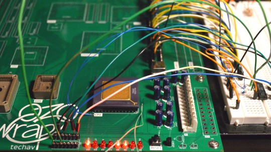

The CPU free run test is an important one. It confirms the most basic functions of the board and the CPU are functional. A board that can't free run at this stage likely has some significant problem that must be solved before anything else will work.
Luckily, it passed this test!
I used the data bus transceiver sockets to attach test wires to, so I could tie all the data bus signals low. On the 68k architecture, $0000,0000 corresponds to the instruction ORI.b #0,D0 which is a 16-bit opcode ($0000) for an OR instruction followed by an immediate constant word ($0000). So for every 32-bit bus access, the CPU is fetching one complete instruction, incrementing the Program Counter by 4, then repeating. The result of the instruction is stored in the D0 register, so nothing is ever written to the bus.
This behaviour can be confirmed with a logic analyzer, but it's easiest to visualize by connecting LEDs to some of the higher address bits and watching them count up in binary (which is what I did here).
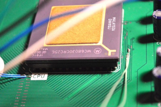
On the 68030 there is a bit more to do than just grounding the data bus. In particular, the CPU's asynchronous bus expects peripherals to report they are ready and have placed valid data on the bus by asserting the Data Strobe Acknowledge signals (DSACKn#). In normal operation, the system will delay asserting these signals to give the peripheral device enough time to do its job, signalling the CPU to insert wait states until the data is ready. For free run though, these signals can be tied low to signal to the CPU that the data it's requesting (all 0s) is ready immediately (because the data bus is tied to ground).
Here is where a last-minute addition to my PCB layout really came in handy. I removed the solder mask on these small sections of important signal traces so I would have a clear place to probe these signals on the top of the board. This also gave me just enough room to solder some 30 gauge wire to the DSACKn# and address signals for running the free run test.
Now that I know the most basic functions of the board are working, I can move on to the next step — running first code. To run real code I'll need ROM working, which will also require the bus controller CPLD to be minimally functional.
I am hoping to have this project at least running BASIC in time to exhibit it at VCF Southwest in Dallas at the end of June this year. I've got a lot of work still to do to reach that goal, but passing these first tests does give me hope that there are no huge show-stopping problems with my PCB (at least nothing that can't be worked around with a bodge wire or two)
#homebrew computing#vintage computing#wrap030 atx#motorola#mc68030#motorola 68k#motorola 68030#vcf southwest#VCFSW
13 notes
·
View notes
Text
That makes complete sense to me!
It's been a real minute since I've written 68k TI-BASIC, I wish I'd remembered/known there were sprite functions when I did this. It's all matrices, For loops and If [CONDITION] Then PtOn [X], [Y} EndIf. Very slow to draw. In my defense, I was trying to do everything without looking at external documentation. :P
The cell state-transition logic is just an xor between the cell's current state and and the state of its neighbor to the left. It almost certainly would've been faster and easier to use sprites like you describe.
The dithered "gray" bit is just:
For j,i+1,WIDTH-1,2 PtOn j-1,HEIGHT-i EndFor
Where i is the current iteration number and WIDTH and HEIGHT are the dimensions of the graph. (xmin and ymin are both set to 0, xmax and ymax are both set to WIDTH-1 and HEIGHT-1, respectively)
Initially I was trying to use NewPic with a list of points, but boy was that unperformant.
Bored in class
33 notes
·
View notes